- Dual-band Circularly Polarized Microstrip Antenna With Small Frequency Ratio
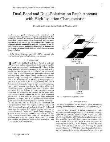
- Dual-band Circularly-polarized Square Microstrip Antenna
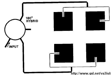
- Single-feed Dual-band Circularly Polarized Microstrip Antenna

- SHARMA, DUAL BAND CIRCULARLY POLARIZED MODIFIED RECTANGULAR PATCH ANTENNA polarization in both bands. An impedance bandwidth of 7.2% in the lower band (2.53 GHz) and 3.6% in the upper band (5.73 GHz) with a 3 dB axial ratio of 2% and 3.2% in the lower and upper band respectively is achieved.
- Patch antenna, the X-band element will include a patch and ground plane separated by Rogers 5870 dielectric with r =2.33. The S-band will include a patch and ground plane separated by Rogers 6010 dielectric with r =10.2. 1.4 Circular Polarization Antennas that are linearly polarized can transmit and receive linearly polarized signals.
- A circularly polarized wave can be in one of two possible states, right circular polarization in which the electric field vector rotates in a right-hand sense with respect to the direction of propagation, and left circular polarization in which the vector rotates in a left-hand sense.
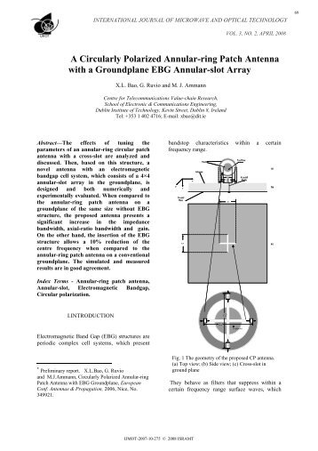
DUAL-BAND CIRCULARLY POLARIZED MICROSTRIP ANTENNA WITH SMALL FREQUENCY RATIO. A novel design of single-feed dual-band circularly polarized patch antenna surrounded by an annular-ring is proposed. Jacquemod, and R. Staraj, Dual-band circularly polarized microstrip antenna for satellite application,' IEEE Antennas.
- About this Journal ·
- Abstracting and Indexing ·
- Aims and Scope ·
- Article Processing Charges ·
- Bibliographic Information ·
- Editorial Board ·
- Editorial Workflow ·
- Publication Ethics ·
- Reviewer Resources ·
- Submit a Manuscript ·
- Subscription Information ·

- Annual Issues ·
- Open Special Issues ·
- Published Special Issues ·
Dual-Frequency Circularly Polarized Truncated Square Aperture Patch Antenna with Slant Strip and L-Shaped Slot for WLAN Applications
Faculty of Engineering, King Mongkut’s Institute of Technology Ladkrabang, Bangkok 10520, Thailand
Correspondence should be addressed to ; moc.liamg@gnowuhcp
Dual-band Circularly Polarized Microstrip Antenna With Small Frequency Ratio
Received 1 March 2018; Revised 31 May 2018; Accepted 4 June 2018; Published 16 July 2018
Academic Editor: N. Nasimuddin
Copyright © 2018 Sorana Niyamanon et al. This is an open access article distributed under the Creative Commons Attribution License, which permits unrestricted use, distribution, and reproduction in any medium, provided the original work is properly cited.
Abstract

This research proposes a dual-frequency circularly polarized truncated square aperture patch antenna with slant stripline and L-shaped slot for WLAN applications. In the antenna design, the parameters were optimized and the WLAN-enabled dual-frequency (2.4 and 5.8 GHz) antenna was realized. Simulations were subsequently carried out for the impedance bandwidth () < −10 dB, axial ratio (AR) ≤ 3 dB, optimal gain, and bidirectional radiation pattern. To validate, an antenna prototype was fabricated and the experiments were undertaken. The simulated and experimental results are in good agreement. In essence, the proposed WLAN-enabled dual-frequency circularly polarized antenna is most suited for applications in the vertically and horizontally elongated areas, including in the tunnel, train carriage, and buildings.
1. Introduction
Recent decades have witnessed exponential growth in the utilization of circularly polarized (CP) antennas in wireless communications. The wider adoption of CP technology is attributable to alignment variability (i.e., horizontal, vertical, and diagonal) of the receiving antenna with reliable performance [1]. Previous research has experimented with diverse antenna structures to produce circular polarization (CP) [2–21].
One of the most important characteristic of the antenna is the bandwidth. There are various techniques developed solely for the bandwidth enhancement. The printed wide-slot antenna fed by a microstrip line [2] achieves a wide impedance bandwidth with a very simple structure consisting of a feeding strip and a square slot on the opposite site of an FR4 substrate. The bandwidth of wide-slot antenna can still be enhanced by introducing defected ground structure [3], using fractal-shaped slot [4].
Another important characteristic of the antenna is the polarization. Since mobile device used in the wireless communication system such as W-LAN application does not have a static placement, circularly polarized antenna is implemented in order to ensure that the receiver will always be able to pick up transmitted signal regardless of its positioning. The circular polarization characteristic of the antenna can be created by using two feeding ports with a difference in phase of 90 degrees [5]. However, the complexity of two feeding ports can be adjusted into one feeding port with an unequally split feeding structure [6, 7], modifying the feeding structure into an S-shape [8], or using sequential rotation feeding structure [9] instead. Nevertheless, instead of changing the feeding structure of the antenna, there are many different methods that could also result in the antenna being circularly polarized such as the modification of the slot structure using various shape slits [10], adding a pair of inverted L [11], implementing truncated corners [12], introducing a parasitic patch [13, 14], placing a parasitic unequal linear slots [15], T-shaped slot [16], or S-shaped slot [17], using two-diode controlled slot [18], and changing the main slot structure into a set of small square slots with multiple rectangular arms [19].
Nevertheless, W-LAN application operated on two frequency bands. Thus, the antenna must also have a dual-band characteristic. The stacked antenna [20] uses two circularly polarized antennas of the different frequency band with good isolation together. There is also the antenna [21] that used a stacked patch and U-slot to achieve dual-band circularly polarized characteristic. However, stacking many elements together leads to an increase in overall size of the antenna.
This experimental research thus proposes a dual-frequency (2.4 and 5.8 GHz) circularly polarized truncated square aperture patch antenna with slant stripline and L-shaped slot for WLAN applications. In the antenna evolution, a wide slot technique is utilized to realize the antenna minimization, the impedance bandwidth enhancement, and a bidirectional radiation pattern. The stripline rotation and L-shaped slot are incorporated to manipulate the antenna’s surface current directions for circular polarization (CP). The design scheme aims to achieve the compact, cost-effective, circularly polarized dual-frequency operable antenna with satisfactory gains. A valuable improvement in axial ratio bandwidth is achieved with the proposed technique. The antenna is able to obtain the simulated and experimental lower-band axial ratios (AR) which were, respectively, 1.48 dB and 1.62 dB, with the corresponding bandwidths of 6.1% and 3.7%, while those of the upper band were 0.66 dB and 0.54 dB with the corresponding bandwidths of 8.4% and 6.0%.
Dual-band Circularly-polarized Square Microstrip Antenna
The organization of the research paper is as follows: Section 1 is the introduction. Section 2 discusses the antenna structure and evolution with the simulation results of the proposed dual-band CP antenna. Section 3 compares the simulation and experimental results. The concluding remarks are provided in Section 4.
2. Antenna Structure and Evolution
Single-feed Dual-band Circularly Polarized Microstrip Antenna
Figure 1 illustrates the initial structure of the proposed antenna (antenna A). The antenna is designed on FR-4 substrate with a relative permittivity () of 4.3 and loss tangent () of 0.02. The antenna has a width () × length () × thickness () of 40 mm × 54 mm × 1.6 mm. On the front side of the antenna, there is a microstrip feed line with a width () × length () of 3.1 mm × 19 mm, which is a transmission line with an impedance of 50 Ω. A truncated square aperture slot is located on another side of the FR-4 substrate. The slot has a size of 23 mm × 23 mm with the chamfer width () of 3.5 mm and chamfer angle () of 45°. Performance of the antenna is shown in Figure 2. The current stage of antenna is single band and has linear polarization, which could be further improved.